Parallax Mapping in Unity URP: Offsetting UVs by View Direction
Normal mapping cannot show bumps occluding each other. Parallax mapping fixes that with a one-line UV offset — and here is where the approximation breaks.
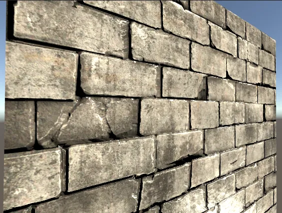
In the previous article I covered normal mapping: sample a normal per pixel, light the surface with it, and flat geometry starts to look like it has relief.
That works, but only up to a point. Because the geometry never actually changes, moving the camera close to the surface makes the illusion collapse. The reason is specific:
If the surface really had bumps, you would see them occlude one another as the view angle changes. Without that, what you get is a flat plane with shading painted on it.
— 3D Graphics Maniax #17: beyond bump mapping (1), parallax mapping, Mynavi News (Japanese)
Parallax mapping is the technique that addresses this.
Height maps
Parallax mapping needs a height map: a texture where white means high and black means low. It stores the elevation of the surface directly, rather than the derived slope that a normal map stores.
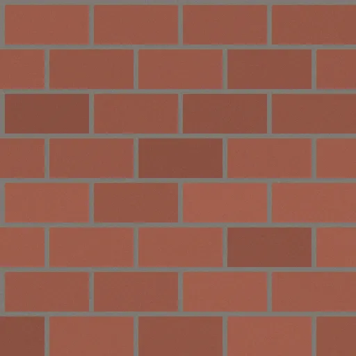
Base map
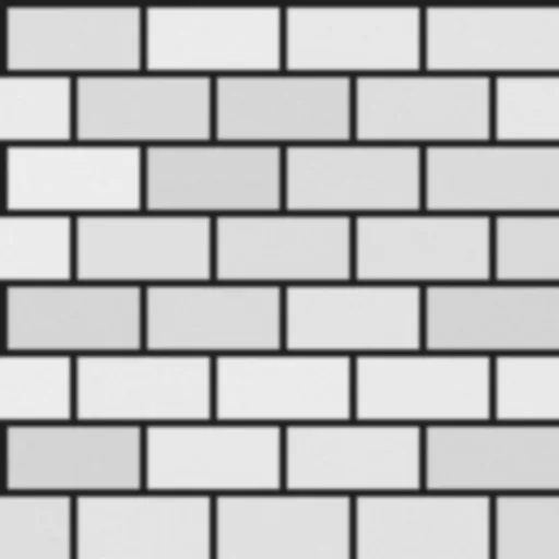
Height map
Conveniently, this costs nothing extra in an art pipeline — the height map is usually already there, because it is what the normal map was generated from in the first place.
Why normal mapping looks wrong, and what to do about it
Standard normal mapping samples the textures at the UV coordinate the rasterizer handed it. It never accounts for the view direction hitting a raised part of the surface before reaching that point.
If occlusion were taken into account, the sample would have to move along the view direction. That is precisely what parallax mapping does:
- Sample the height map at the UV that normal mapping would have used.
- Scale that height by a constant and offset the UV along the view direction.
- Sample the base color and normal map at the offset UV.
The constant is picked by eye: apply the shader, look at the object, and tune until it reads correctly.
Why a constant is good enough
An approximation this crude working at all deserves an explanation. It rests on one assumption:
When the surface relief is assumed to be very gently sloped, the height at the pixel being shaded and the height where the view ray actually intersects the relief are close enough to be treated as the same value.
— 3D Graphics Maniax #17, Mynavi News (Japanese)
Under that assumption, parallax mapping really is accounting for occlusion — the error just stays small enough not to matter.
Which also tells you exactly when it fails. When the relief is steep, the offset computed from the local height diverges sharply from where the ray truly intersects:
So parallax mapping is a good approximation for gentle relief, and a poor one for anything sharp. Techniques that trace the height field properly — parallax occlusion mapping and friends — are the answer there, and the subject of the next article in this series.
Implementation
- Repository: HelloCG-creative/Shader
- This shader:
ParallaxMapping.shader
Full shader
Shader "Unlit/ParallaxlMapping"{    Properties    {        _MainTex ("Texture", 2D) = "white" {}        [Normal] _NormalMap("NormalMap", 2D) = "bump"        _HeightMap("HeightMap", 2D) = "white"{}        _Shininess("Shininess", Float) = 0.07        _HeightFactor("HeightFactor", Float) = 0.5    }    SubShader    {        Tags { "Queue"="Geometry" "RenderType"="Opaque" "RenderPipeline"="UniversalPipeline"}        LOD 100
        Pass        {            Name "Normal"            Tags { "LightMode"="UniversalForward"}
            HLSLPROGRAM            #pragma vertex vert            #pragma fragment frag            #pragma multi_compile_fog
            #include "Packages/com.unity.render-pipelines.universal/ShaderLibrary/Core.hlsl"            #include "Packages/com.unity.render-pipelines.universal/ShaderLibrary/Lighting.hlsl"
            struct appdata            {                float4 vertex : POSITION;                float2 uv : TEXCOORD0;                float3 normal : NORMAL;                float4 tangent : TANGENT;            };
            struct v2f            {                float2 uv : TEXCOORD0;                float4 vertex : SV_POSITION;                float3 viewDirTS : TEXCOORD1;                float3 lightDir : TEXCOORD2;                float3 lightColor : COLOR;            };
            TEXTURE2D(_MainTex);            SAMPLER(sampler_MainTex);
            TEXTURE2D(_NormalMap);            SAMPLER(sampler_NormalMap);
            TEXTURE2D(_HeightMap);            SAMPLER(sampler_HeightMap);
            float _Shininess;            float _HeightFactor;
            CBUFFER_START(UnityPerMaterial)            float4 _MainTex_ST;            float4 _NormalMap_ST;            float4 _HeightMap_ST;            CBUFFER_END
            v2f vert (appdata v)            {                v2f o;                o.vertex = TransformObjectToHClip(v.vertex.xyz);                o.uv = TRANSFORM_TEX(v.uv, _MainTex);
                float3 binormal = cross(normalize(v.normal), normalize(v.tangent.xyz)) * v.tangent.w;                float3x3 rotation = float3x3(v.tangent.xyz, binormal, v.normal);
                Light light = GetMainLight();
                // Same as the normal mapping shader: move the light and view                // vectors into tangent space once per vertex.                o.lightDir = mul(rotation, light.direction);                o.viewDirTS = mul(rotation, GetObjectSpaceNormalizeViewDir(v.vertex));                o.lightColor = light.color;                return o;            }
            float4 frag (v2f i) : SV_Target            {                i.lightDir = normalize(i.lightDir);                i.viewDirTS = normalize(i.viewDirTS);                float3 halfVec = normalize(i.lightDir + i.viewDirTS);
                // Sample the height map and shift the UV along the view direction.                float4 height = SAMPLE_TEXTURE2D(_HeightMap, sampler_HeightMap, i.uv);                i.uv += i.viewDirTS.xy * height.r * _HeightFactor;
                float4 tex = SAMPLE_TEXTURE2D(_MainTex, sampler_MainTex, i.uv);                float3 normal = UnpackNormal(SAMPLE_TEXTURE2D(_NormalMap, sampler_NormalMap, i.uv));
                normal = normalize(normal);
                float4 color;                float3 diffuse = max(0, dot(normal, i.lightDir)) * i.lightColor;                float3 specular = pow(max(0, dot(normal, halfVec)), _Shininess * 128) * i.lightColor;
                color.rgb = tex * diffuse + specular;
                return color;            }            ENDHLSL        }    }}
Walkthrough
The vertex shader is unchanged from the normal mapping version — the tangent-space basis is built the same way, and the light and view vectors are transformed the same way. The entire difference lives in two lines of the pixel shader:
// Sample the height map and shift the UV along the view direction.float4 height = SAMPLE_TEXTURE2D(_HeightMap, sampler_HeightMap, i.uv);i.uv += i.viewDirTS.xy * height.r * _HeightFactor;i.viewDirTS.xy is the view direction projected onto the tangent plane — the direction the sample
should slide in. height.r is the elevation at the current UV, and _HeightFactor is the tuning
constant from the diagrams above.
Everything after that is identical to normal mapping. It just reads from a shifted UV.
Results
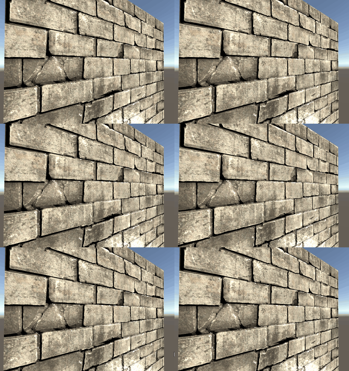
The wall rendered with parallax mapping:
Compared directly against normal mapping — the difference is subtle in a still frame:
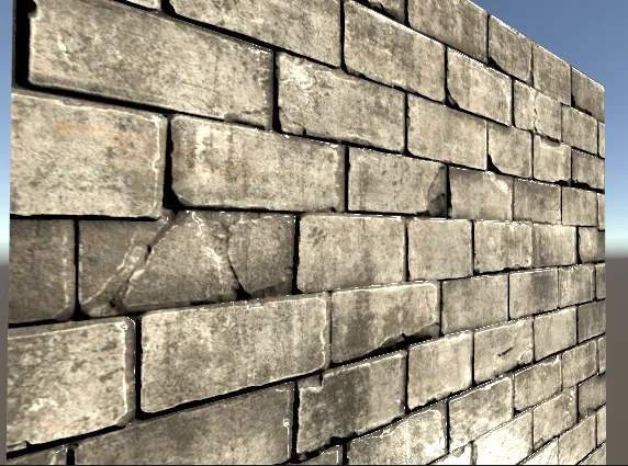
In motion it is much more obvious, because parallax is fundamentally a motion cue — the sampling offset changes with the view direction, so the surface features shift against each other the way real relief would: